Building a BIQUAD Antenna
Introduction
Being a CS student, I found the internet an invaluable resource for helping me with work. The problem is that the two places where I have my lectures (the top floor of the building and the bottom basement) have no wireless Access Points (most of which are spread in the middle). As such I needed a way of extending my laptop card's wireless range. Some wireless cards have connections for external antennas, mine unfortunately does not, so I had to modify it to take an external antenna. This guide deals with the construction of the antenna itself, which can be used on any card with a connector attached (be it an original connector or one you added yourself).
The concept of a BIQUAD
For a really good grounding in radio transmission (be it 802.11b or anything else), get hold of a copy of the ARRL (American Radio Relay League) handbook. It's a good read, and I recommend it for its theory and programs (it comes with programs for modelling signals/antenna behaviour and other useful stuff; unfortunately Windows only, but there are some DOS programs (use dosemu on Linux)).
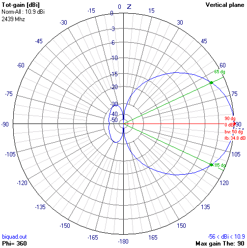
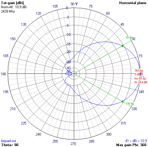
Generally antennas come in two forms, omnidirectional and directional. Omnidirectional antennas radiate the waves all round them. A perfect omnidirectional antenna will radiate energy uniformly in all directions, and is generally shown as a point source (and is known as an Isotropic antenna). Directional antennas focus this energy into a beam. The narrower the beam the more focused the energy (and the less interference is encountered), and the further it will radiate in a particular direction, but the narrower the beam, the harder it is to position and aim the antenna. Omnidirectional antennas need little to no positioning. Provided you are within the radius of the signal, you can pick it up. Directional antennas need aiming, and the narrower the beam the more precise you must aim. Some directional antennas need to be used with tripods, because of the difficulty in positioning. This BIQUAD (theoretically) can provide ~11dbi (3db is roughly a doubling of power) gain and a beamwidth (bw) of 50 degrees. Note that I say theoretically. How close your antenna comes to this is dependent on the build quality.
Using the 4nec2 program, we can show the radiation pattern for the BIQUAD, both in horizontal (vertical plane) and vertical (horizontal plane) polarisation.
 |
 |
What is the maximum range of a 802.11b/g wireless network?
Actually quite a bit. Granted you will not manage to produce a 125 mile wireless network with this kit, but it does show how far your WiFi can go (apart from the antennas, the hardware was off-the-shelf consumer goods). This antenna will not give you such distances but it should give you increased range. Some people have noted a 5 mile range when two BIQUADs are used on each end (which is not too shabby).
Design
The BIQUAD, as the name implies, consists of two quad antennas together. A reflector (a.k.a ground plane) is also added which provides us with a further gain boost. The design has been posted all over the place, most notable is Trevor Marshall's site which uses a BiQuad antenna as a feed to a parabolic dish (in his case an old Primestar dish).
This Antenna is the first one I ever built, and was based on Trevor's BiQuad, with the exception that this one is designed for standalone use (rather than as a feed). Trevor does mention a standalone BiQuad, but that is in passing. This whole page is dedicated to it.
This antenna is being designed to work with the 802.11b/g frequency range, as such we will be designing it so that the antenna's resonant frequency is the central channel frequency (2.442GHz, channel 7) so as to get a decent performance throughout the range of channels.
The reason that we pick a resonant frequency is because of a thing called reactance. As quoted from Wikipedia “Reactance diverts energy into the reactive field, which causes unwanted currents that heat the antenna and associated wiring, thereby wasting energy without contributing to the radiated output” (could not have said it better myself). To put it simply, reactance is all the energy that is wasted away (be it in heat or other forms), energy that could have been put to better use radiating your signal. As such it is of utmost importance that you minimise your antenna's reactance, and this is achieved by running it at its resonant frequency (or more precisely, designing your antenna for the frequency you need to use), because at this point there is a net zero reactive current.
We are designing an antenna to work with 802.11b WiFi systems. But they do not work on one frequency. Rather there is a set of frequencies for which there are channels 1 to 13 and a range from 2.412GHz to 2.472GHz. So, for which frequency to design the antenna for?
Well, if we design the antenna for channel 1, it will need to operate from 2.412 to 2.472 (0.060GHz). If we rate the signal strength from 1 (the strongest) to 10 (weakest) (we assume that signal strength is due to reactance alone). Then at Channel 1 we would have a signal strength of 1, and at channel 13 the signal strength is 10.
On the other hand, if we were to design the antenna for the middle channel (7). Then at channel 7 we would have a signal strength of 1, at channels 1 and 13 respectively, we would have a signal strength of 5. As you can see, by designing the antenna for the middle channel (2.442GHz), we have improved efficiency on all the other channels.
So we will be working with a frequency of 2.442GHz (2.442 * 109 Hz). What we need to find is the wavelength at this frequency:
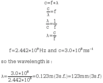
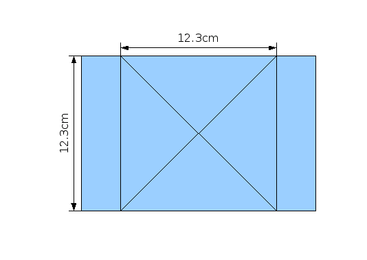
As such the wavelength is 123mm. It is generally recommended that an antenna's ground-plane be at least one wavelength in size. As such our BiQuad base will be 123mm by 123mm.
The dimensions of the Bi-Quad are shown below:
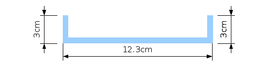
You will need to make this out of a conductor. Usually copper is used. I went with 3mm aluminium. The antenna's dimensions are above. The 3cm sides are at 90o to the base, as seen on this side view diagram above. These 3mm "lips" are not required, but they do reduce sidelobe radiation. I emailed Trevor regarding whether or not they are recommended for use without a dish but have not so far got a reply, so for now I am going to assume they are.
The element itself is made of wire. Contrary to popular belief, the thickness of the wire does matter. The thicker the wire the greater the bandwidth of the antenna. The bandwidth of the antenna dictates the range of frequencies over which an antenna is effective (around the frequency it is being run at at that point in time). Having a thick wire increases the bandwidth, while a thinner one restricts the frequency closer to the frequency being run at.
Theoretically you could have an antenna with a high enough bandwidth to detect all of the wireless channels simultaneously. So why do we not do this? Well, because if we want to connect to a wireless network on channel 4, we are going to get a lot of interference from all other other channels at the same time, thereby reducing the range of the antenna (not to mention that every time to transmit, you will flood the nearby channels as well, basically making life difficult for everyone).
An antenna with a large bandwidth theoretically could make a good short-range stumbling rig. You could set your card to the mid-channel (7) and let the antenna pick up that and all the other channels at the same time. But as stated beforehand, this antenna would not be capable of very good range, due to interference. So you could detect all the channels simultaneously nearby, or detect networks further away using the channel hopping method (with an antenna with a narrower bandwidth).
Also you must be careful to use wire that is not too thin. Thinner wires have a higher resistance, which can affect the antennas performance. It seems that a good wire diameter is about 1.2mm.
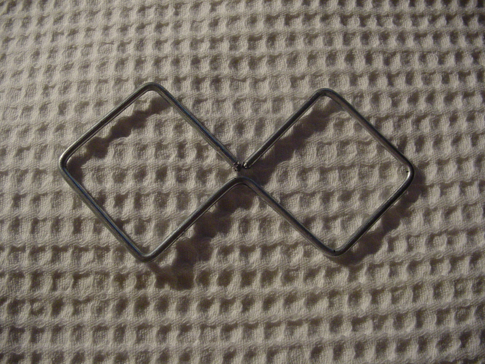
The element involves two quad elements side-by-side (hence the term bi-quad), and the length of the sides is 1/4 of the wavelength, as shown on the diagram below.
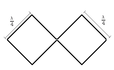
At 2.442GHz this is 123/4 = 30.75mm. So we use 30.75mm for the lengths. 1mm here or there will not make a huge difference, so if you are unable to measure accurately (e.g. If you do not have the equipment to bend wire with 2d.p. accuracy) you can round up or down to 1d.p.
Construction:
The Reflector:
I was lucky in that my dad knew someone who could get me some pre-cut and shaped metal, so he was able to get me the base complete with lips:
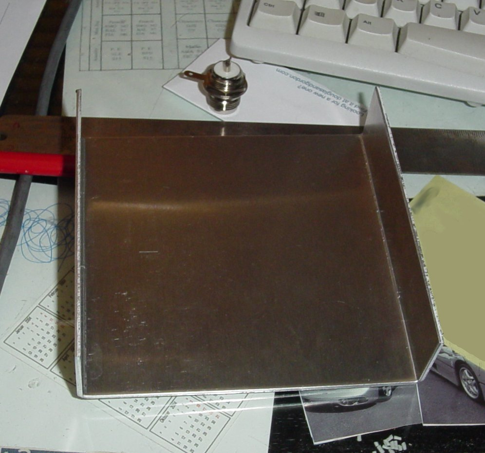
Above the aluminium you can see the female N-connector which I will install into the reflector plate. Next we have to drill a hole for the element/connector. To do this we first mark out onto the reflector the middle, where we will drill our hole. Making a mistake with drilling will be virtually impossible to correct, so triple check!
Once correctly marked out, we can start drilling. I used a 14mm drill bit with a drill press because the N-connector was 13mm in diameter. I recommend you start off with a smaller bit, and gradually work your way up to the desired size.
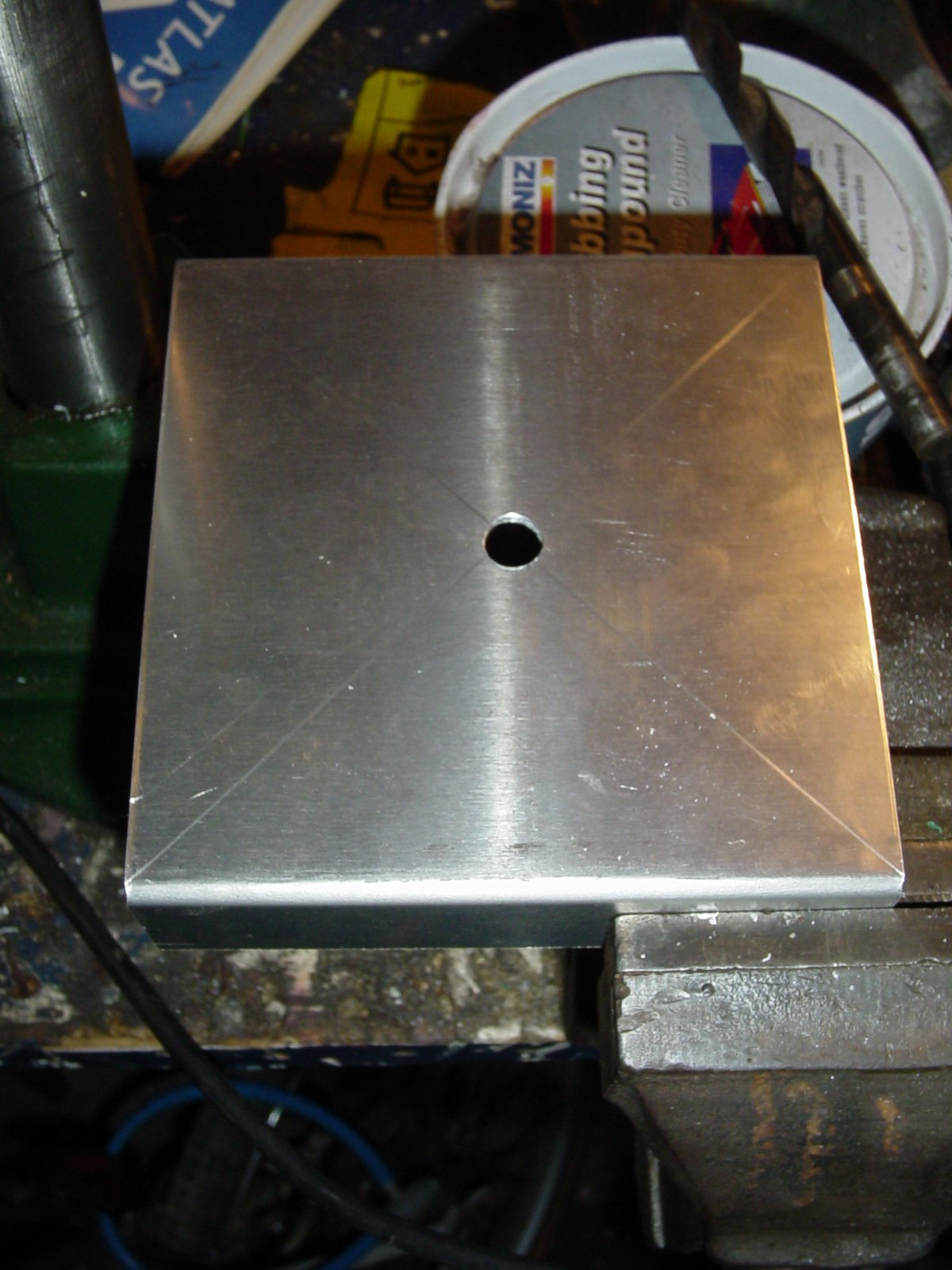
Once done we have the hole, where we will fit in the N-connector.
Then you attach the N-connector:
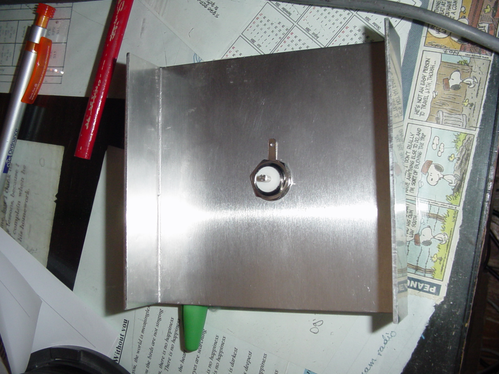
The element nut was tightened using a spanner.
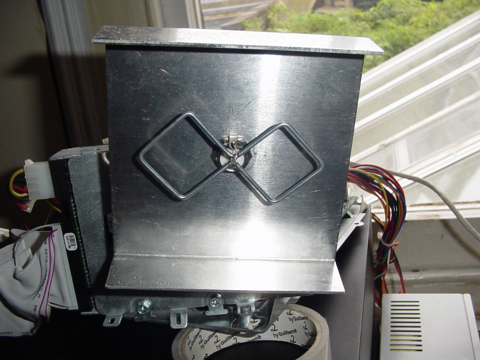
The element:
Our element is made out of an old coat hanger. Yes, it is a bit strange. The metal from the coathanger was very stiff, which means that once bent, it is more likely to stay in shape. When I originally tried using copper wire, I found that it was too easy to bend it out of shape, which would impair the antennas performance. At 2.5mm this wire was a bit thick, but for me the tradeoff in range for a more robust build was a good one. This may not be the case for you (e.g. Your antenna will be encased) so feel free to use another wire thickness.
Our Element once bent into shape:
And here it is attached to the reflector.
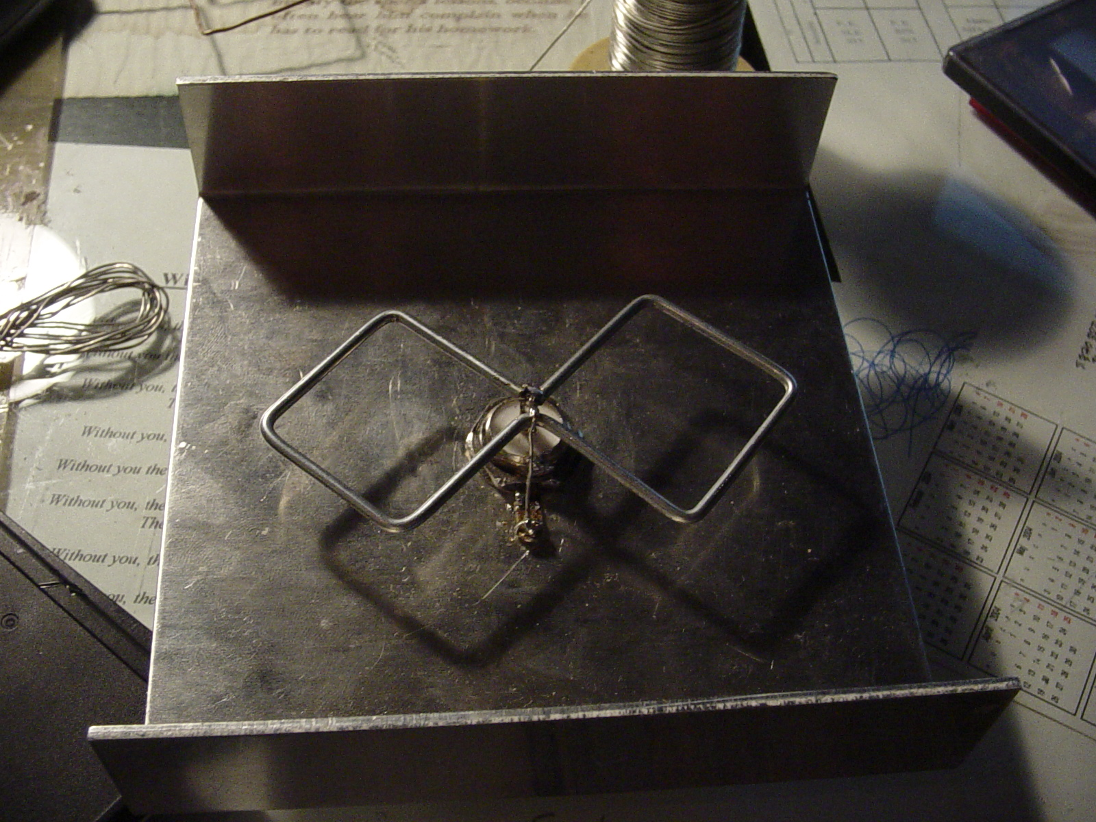
Side view. Notice how straight the element is. This is due to the stiffness of the wire, and is one of the reasons I picked thicker wire. I could not do this with the copper, as it was too flexible.
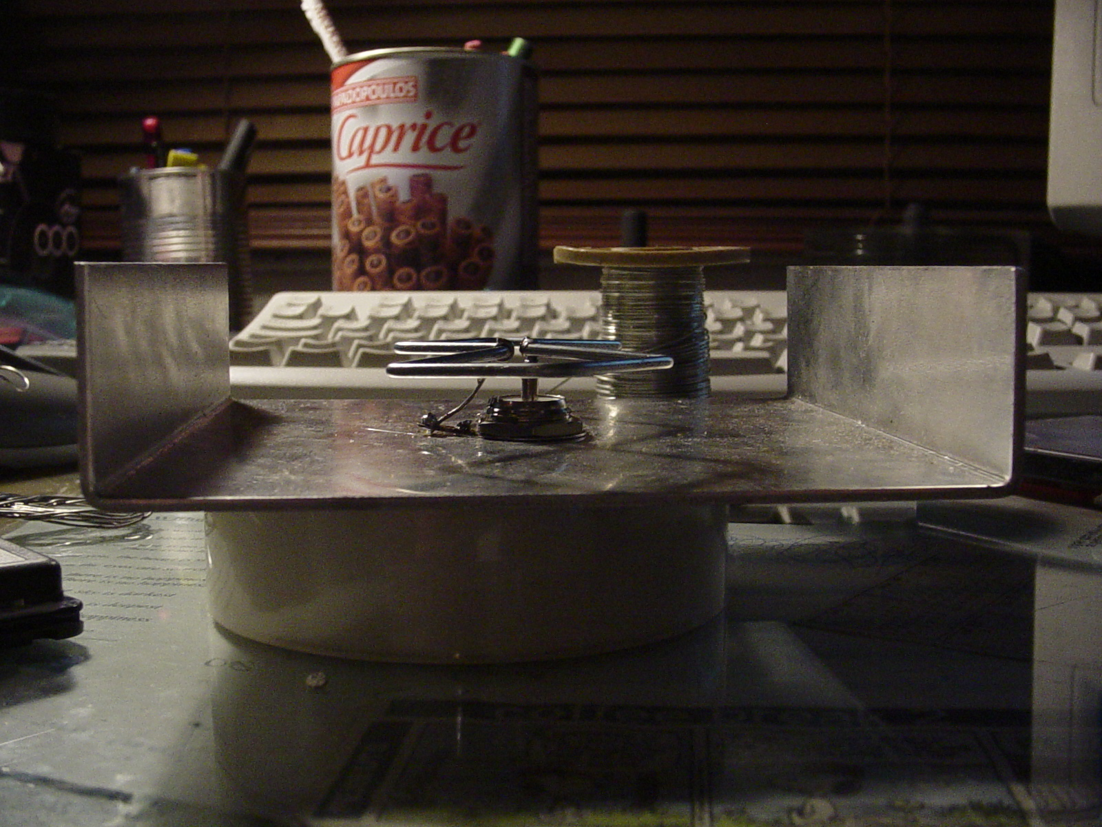
And here is the finished product:
Testing:
The antenna was tested on a Netgear 802.11b PCI card and my KCorp cardbus card. The antenna has definitely improved performance, as I can now access my home AP from my garden (has never been possible due to a lot of walls being in the way) and I can get internet access from the top floor of my uni (the AP being 5 floors down) and the 3rd floor basement (which has at least 10m between the antenna and the access point).
The only issue I see is that when I am stumbling and lock my card to a particular channel, I will pick up channels above and below. So for example, I set my card to fixed channel 4, I would also get channel 2 and 6 showing up as well. I think this is due to the issue of the wire thickness. I thought I would test this out.
Wire thickness test:
Well, I decided to see what would happen if I used thinner wire for the element. This was to see if I could prevent the 'channel spillage' I was getting while stumbling.
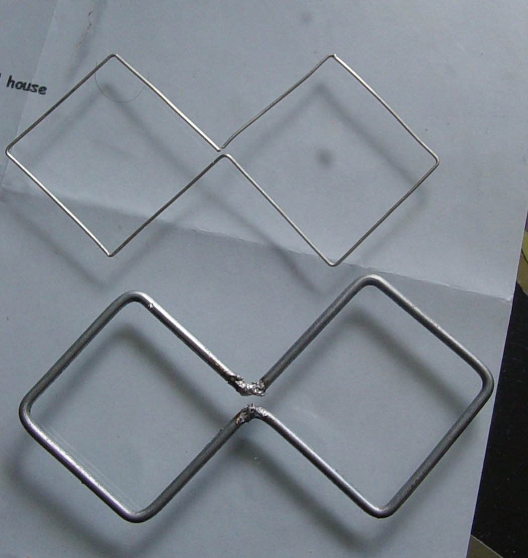
The bottom wire is the original, and the top one is the new thinner wire. I installed the thinner wire and fired up my card to see how it was working.
First impressions were promising, when locked onto a channel I no longer got other channels showing up, which was good. Unfortunately I found that lots of 'phantom' sites were coming up on kismet. These are networks which have '
Also, connecting to a network was interesting. I would get a higher signal strength level, but the data rate would stay low (about 2mbit/s). Checking the stats showed me a large number of errors, leading to me to think that while the thinner wire was providing a narrower bandwidth and hence stronger signal level, it was negatively affecting reception/transmission quality. I believe that this may be due to increased resistance (as stated before) in the element. This wire was very thin, thinner than the 1.2mm other people have recommended. Note that I have speculated as to the causes; if someone out there who is more knowledgable than me can clear this up, feel free to correct me (always keen to learn).
All in all a healthy 'in between' thickness would be perfect, but for me I will be going with the thicker wire for now.
References:
http://en.wikipedia.org/wiki/Antenna_(radio)
http://trevormarshall.com/biquad.htm
Note that some of the references are contained within the text itself (as links).


